
Here you are, hopefully this helps.
After removing the 3 screws on the bottom of D10 to remove the shell there are two more to remove the engine assembly.
Once that is out you should have this:
![[Image: 61F1ADE4-00F2-41A5-B4F0-B8D49BAEE1BA_zpsgq95kank.jpg]](http://i300.photobucket.com/albums/nn5/dawsona17/61F1ADE4-00F2-41A5-B4F0-B8D49BAEE1BA_zpsgq95kank.jpg)
You now need to remove the weights at the rear and side, and it should look like this:
![[Image: 89E6D91D-4F73-4E6C-9475-B594917DAEF6_zpssjzl1u5k.jpg]](http://i300.photobucket.com/albums/nn5/dawsona17/89E6D91D-4F73-4E6C-9475-B594917DAEF6_zpssjzl1u5k.jpg)
There are 3 screws to remove:
![[Image: CA534238-5ED4-4905-83D4-023F43905D71_zpsh04yqpui.jpg]](http://i300.photobucket.com/albums/nn5/dawsona17/CA534238-5ED4-4905-83D4-023F43905D71_zpsh04yqpui.jpg)
Now you should have this, make note of the gears and how the go in:
![[Image: 90B60350-DD0D-4AAB-AF49-0295F63EF624_zpsvbblrrsn.jpg]](http://i300.photobucket.com/albums/nn5/dawsona17/90B60350-DD0D-4AAB-AF49-0295F63EF624_zpsvbblrrsn.jpg)
You can now de-solder the motor and solder in the new one. In my expierence the ground and the resistor are not needed but use them if you can.
![[Image: DBAC7D40-7D9C-4B45-A883-F73E5DD951AF_zpsjfdwkic6.jpg]](http://i300.photobucket.com/albums/nn5/dawsona17/DBAC7D40-7D9C-4B45-A883-F73E5DD951AF_zpsjfdwkic6.jpg)
Other than the gears being right you have to get the activation mechinisim and sprin right, it should look like this:
![[Image: 2E905600-85E4-482E-B8F4-2FA24CE511C6_zpszraajg7g.jpg]](http://i300.photobucket.com/albums/nn5/dawsona17/2E905600-85E4-482E-B8F4-2FA24CE511C6_zpszraajg7g.jpg)
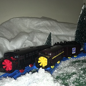
And now back together:
![[Image: 41A7F1E0-CC29-45F1-A642-2814C1ACCFCB_zpsaupmfqrz.jpg]](http://i300.photobucket.com/albums/nn5/dawsona17/41A7F1E0-CC29-45F1-A642-2814C1ACCFCB_zpsaupmfqrz.jpg)
Here is a shot of the circuit board. Note the red wire is the (+) connection and the lower bottom hole is for the (-) wire which is missing on this one.
![[Image: 0956ABD4-0ECA-42A4-B44B-D66423459B84_zpsykk3hg7o.jpg]](http://i300.photobucket.com/albums/nn5/dawsona17/0956ABD4-0ECA-42A4-B44B-D66423459B84_zpsykk3hg7o.jpg)
This D10 was one missing the Splatter that I won in an auction this is not fully connected but works fine when connected to a battery.
After removing the 3 screws on the bottom of D10 to remove the shell there are two more to remove the engine assembly.
Once that is out you should have this:
![[Image: 61F1ADE4-00F2-41A5-B4F0-B8D49BAEE1BA_zpsgq95kank.jpg]](http://s300.photobucket.com/user/dawsona17/media/61F1ADE4-00F2-41A5-B4F0-B8D49BAEE1BA_zpsgq95kank.jpg.html)
You now need to remove the weights at the rear and side, and it should look like this:
![[Image: 89E6D91D-4F73-4E6C-9475-B594917DAEF6_zpssjzl1u5k.jpg]](http://s300.photobucket.com/user/dawsona17/media/89E6D91D-4F73-4E6C-9475-B594917DAEF6_zpssjzl1u5k.jpg.html)
There are 3 screws to remove:
![[Image: CA534238-5ED4-4905-83D4-023F43905D71_zpsh04yqpui.jpg]](http://s300.photobucket.com/user/dawsona17/media/CA534238-5ED4-4905-83D4-023F43905D71_zpsh04yqpui.jpg.html)
Now you should have this, make note of the gears and how the go in:
![[Image: 90B60350-DD0D-4AAB-AF49-0295F63EF624_zpsvbblrrsn.jpg]](http://s300.photobucket.com/user/dawsona17/media/90B60350-DD0D-4AAB-AF49-0295F63EF624_zpsvbblrrsn.jpg.html)
You can now de-solder the motor and solder in the new one. In my expierence the ground and the resistor are not needed but use them if you can.
![[Image: DBAC7D40-7D9C-4B45-A883-F73E5DD951AF_zpsjfdwkic6.jpg]](http://s300.photobucket.com/user/dawsona17/media/DBAC7D40-7D9C-4B45-A883-F73E5DD951AF_zpsjfdwkic6.jpg.html)
Other than the gears being right you have to get the activation mechinisim and sprin right, it should look like this:
![[Image: 2E905600-85E4-482E-B8F4-2FA24CE511C6_zpszraajg7g.jpg]](http://s300.photobucket.com/user/dawsona17/media/2E905600-85E4-482E-B8F4-2FA24CE511C6_zpszraajg7g.jpg.html)
And now back together:
![[Image: 41A7F1E0-CC29-45F1-A642-2814C1ACCFCB_zpsaupmfqrz.jpg]](http://s300.photobucket.com/user/dawsona17/media/41A7F1E0-CC29-45F1-A642-2814C1ACCFCB_zpsaupmfqrz.jpg.html)
Here is a shot of the circuit board. Note the red wire is the (+) connection and the lower bottom hole is for the (-) wire which is missing on this one.
![[Image: 0956ABD4-0ECA-42A4-B44B-D66423459B84_zpsykk3hg7o.jpg]](http://s300.photobucket.com/user/dawsona17/media/0956ABD4-0ECA-42A4-B44B-D66423459B84_zpsykk3hg7o.jpg.html)
This D10 was one missing the Splatter that I won in an auction this is not fully connected but works fine when connected to a battery.
![[-]](https://www.blueplastictracks.org/images/collapse.png)